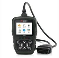
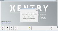
Volvo VIDA/DiCE and Xenon lights auto adjustment
This is my experience of auto adjustment of Xenon lights.
Related Contents:
How to install VIDA2014D on Windows 8.1 / 10 Pro / Core x86 / x64 PC?
Multilingual VXDIAG Nano VOLVO Vida 2014D Win 7 8 10 free download
How to use Volvo Vida Dice 2014D to disable DRL light on Volvo XC90?
If a light motor fails, is there a default position the light fall to, to ensure that oncoming traffic are not dazzled?? ( mine, despite several SUM calibrations keep returning to a very low setting on one light)
If a 12v supply is run across the + and – terminal, would the motor be expected to run? – there are three terminals
Is this a way to test if a motor has failed?
Control modules have been read by DIce/VIda and are apart from a low emergency phone battery fault free. When doing a SUM calibration, DIce/Vida does not like the voltage from the LH ride height sensor – saying its too high.(@3.94v) I have read on a forum that the l/h sensor feeds the range adjustment setup and the r/h sensor feed the 4C shocks – but i’m unsure if that is 100% true
Historically, I lifted the left side of the car until the reading was <3.5v and calibrated which Vida/Dice is happy about. However soon after recalibration the o/s light reverted to a low setting. Now the light does not appear to move due to suspension movement, hence my original question about how to tell if a motor had gone bad.
I have discovered that there is a position sensor fitted to the reflector, which explains perhaps why the light drops back to a low setting shortly after manually lifting them. I have now ordered a L/H position sensor and will fit that before deciding whether to buy a new motor.
I have now finally got this sorted out.
New rear sensor did not sort it, so bought new motor for headlamp.
Good dip beam lighting now restored.
I leaned however our “R” for Xenons motors are much more expensive to buy than the normal halogen motors fitted to the rest of the V70 range, and harder ro get 2nd hand.
The only difference myself and another forum member in the Uk could find was the “post” which fits into the reflector housing is bigger in the Xenons than the halogens.
The small post pulls through the reflector unit
Stripping the motors down to swap the “post” over is relatively simple compared to some jobs I have done on my “R”.
On my “faulty motor” when I stripped the unit I found to motor had seized but after using my finger to rotate the motor a little and a std 9v radio battery to run it for
several minutes in each direction, I now appear to have a viable spare motor 🙂
The last

This is the only picture I took – after I disassembled it. Its all straight forward. Once the unit has the back removed the PCB is removed by remelting the two plastic legs which run up through the PCB. It then lifts up being careful to firstly unclip the pin from the PCB leg. The worm drive is located on two recesses at each end, just gently lever the motor end out first.
All that remains is to get the reflector unit out, which is removed by rotating the large white geared wheel, which releases the unit. The central pin which locates in the actual reflector and is adjusted by the 6mm white dome nut on the motor top can then be removed. .
There is no reason to do this as the reflector unit can be transferred as is to a new light motor.
The small electric motor is a snap in snap out. I levered mine out on the shaft.
Initially took me 30 minutes to disassemble as I was being careful not to damage / break anything – next one will be 3 mins max.
Cheers
Bob
- US$2,552.00 / piece
- US$45.00 / piece
- US$16.99 / piece
- US$59.99 / piece
- US$659.00 / piece
- US$129.00 / piece
- US$75.99 / piece
- US$4.99 / piece
- US$36.99 / piece
- US$30.00 / piece
- US$39.00 / piece
- US$149.00 / piece

